
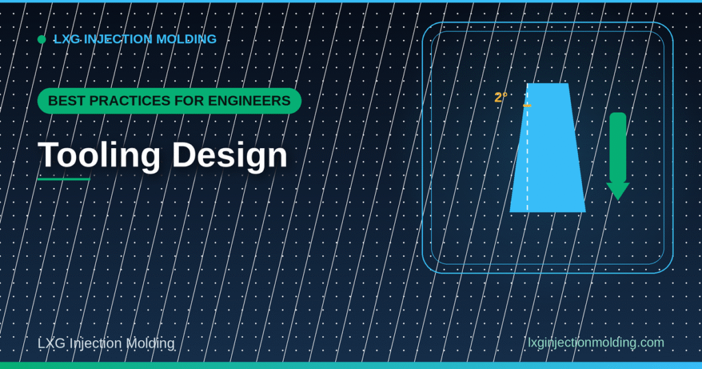
Best Practices for Engineers: Tooling Design
Summary
Tooling design decisions made early in a program – draft angle, parting line placement, how undercuts are handled – have outsized consequences for tool cost, cycle time, and how easily parts eject cleanly shot after shot. Many of these decisions are easiest and cheapest to get right before the part design is frozen, and expensive or impossible to fully correct once a tool is already cut. This guide covers the best practices worth building into tooling design from the start, with a particular focus on draft angle, undercut handling, and parting line strategy.
Key Takeaways
- Minimum draft angle guidelines: 2° for exterior walls, 3° for interior walls and undercuts.
- Textured surfaces need additional draft – roughly 1 to 2° for every 0.001 inch (0.025mm) of texture depth.
- Deep cavities need proportionally more draft than shallow ones to eject cleanly.
- Undercuts are handled through slides and cams, lifters, or collapsible cores and unscrewing molds, depending on undercut type and location.
- Strategic parting line placement can sometimes eliminate external undercuts entirely, reducing tooling complexity.
- Involving toolmakers during the design stage, not after, is what makes these simplifications possible.
Best Practice 1: Apply Adequate Draft Angle
| Surface Type | Minimum Draft Angle |
|---|---|
| Exterior walls | 2° |
| Interior walls / undercuts | 3° |
| Textured surfaces | Add 1–2° per 0.001 inch (0.025mm) of texture depth |
| Deep cavities | Increase draft proportionally to depth |
Draft angle is the slight taper applied to a molded part’s vertical walls that allows it to release cleanly from the mold during ejection. Insufficient draft is one of the most common tooling design mistakes, since it is tempting to specify the minimum angle possible to maximize usable part volume, but a part with too little draft drags against the cavity wall during ejection, risking surface damage, warping, or outright sticking that stops production. Textured surfaces need particular attention, since texture depth effectively reduces the clearance a given draft angle provides, requiring additional draft to compensate.
Best Practice 2: Choose the Right Undercut Strategy
| Strategy | Best For |
|---|---|
| Slides and cams | External undercuts positioned at or near the parting line |
| Lifters | Undercuts that need a mechanical component to withdraw before ejection |
| Collapsible cores and unscrewing molds | Internal undercuts and molded-in threads |
Undercuts – features that would otherwise prevent the part from being pulled straight out of the mold – are one of the biggest drivers of tooling complexity and cost. Each of the three strategies above adds mechanical complexity to the tool, and choosing the right one for a specific undercut, rather than defaulting to whichever approach a toolmaker is most familiar with, keeps tooling cost and cycle time proportional to what the undercut actually requires.
Working through undercut strategy for a new part?
Share your part geometry and we’ll help you evaluate slides, lifters, or collapsible cores against your design.
Best Practice 3: Use Parting Line Placement to Simplify the Tool
Strategic parting line placement can sometimes eliminate the need for an external undercut mechanism entirely, simply by positioning the parting line so the feature in question splits naturally across both mold halves rather than requiring a slide or lifter to form it. This only works, though, when toolmakers are involved during the design stage rather than handed a finished part design to tool as specified. Early collaboration between part designers and toolmakers is what surfaces these simplification opportunities before the geometry is locked in.
Best Practice 4: Maintain Uniform Wall Thickness
Uniform wall thickness is a tooling design consideration as much as a part design one, since uneven walls drive uneven cooling, which in turn drives warpage that no amount of careful tooling can fully correct after the fact. Flagging wall thickness inconsistencies during tooling design review, before cutting steel, gives the design team a chance to revise the part rather than discovering the warpage problem only after first samples come off a finished tool.
Need a tooling design review before committing to steel?
Send us your part drawing and we’ll help flag draft, undercut, and wall thickness issues before tooling begins.
Best Practice 5: Standardize Features Where Possible
Using standardized threads, snap fits, and other common features, rather than custom geometry for every individual requirement, reduces both tooling cost and risk. Standard features have known, well-understood tooling solutions and established design guidelines, while custom geometry requires the toolmaker to solve a problem from scratch each time. Evaluating whether a feature genuinely needs to be custom, or whether a standardized approach would serve the same function, is worth doing deliberately rather than defaulting to custom geometry out of habit.
Best Practice 6: Plan for Ejection Force, Not Just Draft
Draft angle gets most of the attention in tooling design discussions, but ejection force is the broader question draft angle is really answering. A part with technically adequate draft can still eject poorly if it has large flat surfaces with high surface area in contact with the cavity, deep ribs that grip tightly as they cool and shrink onto core pins, or a surface finish that increases friction beyond what the draft angle was calculated to overcome. Reviewing ejection force holistically, rather than checking draft angle as an isolated checkbox, catches problems that a pure draft-angle review would miss.
Ejector pin placement matters here too. Pins should land on the sturdiest sections of a part – typically ribs, bosses, or thicker wall sections – rather than thin flat areas, which can deform, whiten, or punch through under ejection pressure if a design doesn’t have better-supported locations available nearby. Tooling design reviews should walk through proposed ejector pin locations against the part’s wall thickness map before the mold is cut, not after the first ejector pin mark shows up as a defect on a sample part.
Best Practice 7: Account for Shrinkage in Steel Dimensions
| Material Family | Typical Shrinkage Behavior |
|---|---|
| Amorphous resins (ABS, PC, PS) | Lower, more uniform shrinkage, generally easier to predict |
| Semi-crystalline resins (PP, nylon, POM) | Higher shrinkage, often directional and harder to predict |
| Glass-filled or mineral-filled grades | Reduced overall shrinkage but more pronounced directional differences |
Every mold cavity is cut slightly larger than the finished part’s nominal dimensions to compensate for the shrinkage that happens as molten plastic cools and solidifies, and getting that shrinkage allowance wrong is a tooling design mistake that only becomes visible once first samples are measured. Semi-crystalline resins in particular can shrink differently along the flow direction than across it, which means a single uniform shrinkage factor applied to an entire cavity can leave some dimensions in tolerance and others noticeably off. Tooling designers who understand the resin’s crystallinity and expected flow pattern before cutting steel can build directional shrinkage compensation into the cavity rather than relying on a single average figure.
Best Practice 8: Design Cooling Channels Around the Part, Not the Block
Cooling channel layout is sometimes treated as an afterthought once the cavity and core geometry are finalized, but cooling that is routed based on what’s convenient in the steel block, rather than what the part geometry actually needs, produces uneven cooling that drives warpage and extends cycle time as thicker or more complex sections wait to cool down to ejection temperature. Conformal or near-contour cooling channels that follow the part’s actual surface, rather than straight-line channels bored through the block at standard positions, cool complex geometry more evenly and can meaningfully shorten cycle time on parts with varying wall thickness or deep ribs.
How Tooling Design Connects to Other Decisions
Threaded inserts are one of the most common features requiring careful tooling coordination, since insert placement interacts directly with draft angle and ejection strategy around the insert location; our guide to threaded inserts in molded parts covers that intersection. Material choice also affects tooling design decisions, particularly for bio-based resins with different shrinkage behavior than conventional plastics; our guide to bioplastic injection molding covers what that means for tooling.
Machine selection and tooling design need to be coordinated together, since a tool designed without reference to its intended press can run into tonnage or platen-size mismatches; our guide to injection molding machines covers that coordination. And because tooling design directly affects defect rates like internal voids, our guide to voids in plastic parts covers how tooling-related venting and gate decisions connect to that specific defect.
Working With a Supplier on Tooling Design
A molder offering low volume injection molding should involve its toolmakers during part design review, not just at the point of cutting steel, to catch draft, undercut, and parting-line opportunities early. A plastic injection molding company in Norway with strong tooling design discipline should be able to walk through specific draft angle and undercut strategy recommendations for your part, rather than simply quoting whatever tooling approach the part drawing happens to imply.
Conclusion
Good tooling design is mostly a matter of applying well-established best practices consistently – adequate draft angle matched to surface type, the right undercut strategy for each feature, parting line placement that simplifies rather than complicates the tool, and uniform wall thickness – and doing so early enough in the design process that the part geometry can still accommodate them without costly rework. Involving toolmakers at the design stage, rather than after geometry is locked, is the single habit most likely to make all of these best practices actually achievable.
Frequently Asked Questions (FAQs)
What is the minimum draft angle for a molded part?
Generally 2° for exterior walls and 3° for interior walls and undercuts, with additional draft needed for textured surfaces and deep cavities.
How much extra draft does a textured surface need?
Roughly 1 to 2° of additional draft for every 0.001 inch (0.025mm) of texture depth, since texture effectively reduces the clearance a given draft angle provides.
What are the main ways to tool an undercut?
Slides and cams for external undercuts near the parting line, lifters for undercuts needing a mechanical withdrawal before ejection, and collapsible cores or unscrewing molds for internal undercuts and threads.
Can undercuts sometimes be avoided entirely?
Yes, sometimes. Strategic parting line placement can eliminate the need for an external undercut mechanism, but this usually requires involving toolmakers during the design stage rather than after geometry is final.
Why does wall thickness matter for tooling design specifically?
Uneven wall thickness drives uneven cooling and warpage that tooling cannot fully correct after the fact, so catching wall thickness issues during tooling design review is important before cutting steel.
Should every feature on a part be custom-designed?
Not necessarily. Standardized threads, snap fits, and similar features have known tooling solutions and generally cost less and carry less risk than custom geometry solving the same problem from scratch.
Why does ejector pin placement matter if draft angle is already correct?
Adequate draft angle reduces friction during ejection, but ejector pins still need to push against sturdy sections of the part. Pins placed on thin, unsupported areas can deform or punch through the part even when draft angle is otherwise correct.
Does shrinkage allowance differ by material?
Yes. Amorphous resins tend to shrink less and more uniformly, while semi-crystalline resins often shrink more and can shrink differently along versus across the flow direction, which affects how cavity dimensions need to be compensated.
A Beginner’s Guide: Medical Device Molding
A Beginner's Guide: Medical Device Molding Summary Medical device molding involves regulatory, quality, and material requirements that go well beyond...
October 3, 2026
Frequently Asked Questions: Injection Molding Cycle Time
Frequently Asked Questions: Injection Molding Cycle Time Summary Cycle time directly determines how many parts a molding machine can produce...
October 3, 2026
Tips for Choosing the Right Approach: Mold Life Cycle Management
Tips for Choosing the Right Approach: Mold Life Cycle Management Summary Mold life cycle management covers everything from initial tooling...
October 3, 2026

 20+ Years Experience